


Anchor type connectors, also known as built-in internal connection pins, are a type of connection method hidden inside the groove of aluminum profiles. During installation, it is necessary to drill installation process holes at the designated position of the profile, then insert the connecting pin into the profile and connect it to another profile, locking the top thread. Using the displacement generated by the force on the conical positioning pin groove to tighten the connecting pin, thereby achieving the connection between profiles;
>>Dimensions of anchor joint connectors
| Description | Matching Profiles | T (mm) | K (mm) | D (mm) | P (mm) | Unit Weight (g) | Part No. |
|---|---|---|---|---|---|---|---|
| Anchor Connector, Universal | PG30 | 2.2 | 33.0 | 12.0 | 21.0 | 39 | 30.2.01.01 |
| PG40 | 3.0 | 33.0 | 15.0 | 27.0 | 62 | 40.2.01.01 | |
| PG45 | 4.0 | 32.0 | 15.0 | 29.5 | 64 | 45.2.01.01 | |
| PG50 | 4.0 | 32.0 | 15.0 | 32.0 | 66 | 50.2.01.01 | |
| PG60 | 4.0 | 32.0 | 15.0 | 37.0 | 73 | 60.2.01.01 | |
| Slot 10 – PG40 | 4.0 | 32.0 | 15.0 | 27.0 | 62 | 00.2.01.01.02 | |
| Slot 10 – PG45 | 6.0 | 30.0 | 15.0 | 29.5 | 64 | 00.2.01.01.05 | |
| Anchor Connector, Normal | PG30 | 2.2 | 33.0 | 12.0 | 21.0 | 38 | 30.2.01.02 |
| PG40 | 3.0 | 33.0 | 15.0 | 27.0 | 58 | 40.2.01.02 | |
| PG45 | 4.0 | 32.0 | 15.0 | 29.5 | 60 | 45.2.01.02 | |
| PG50 | 4.0 | 32.0 | 15.0 | 32.0 | 62 | 50.2.01.02 | |
| PG60 | 4.0 | 32.0 | 15.0 | 37.0 | 70 | 60.2.01.02 | |
| Slot 10 – PG40 | 4.0 | 32.0 | 15.0 | 27.0 | 58 | 00.2.01.02.02 | |
| Slot 10 – PG45 | 6.0 | 30.0 | 15.0 | 29.5 | 60 | 00.2.01.02.05 | |
| Anchor Connector, Turning | PG30 | 2.2 | 33.0 | 12.0 | 21.0 | 38 | 30.2.01.03 |
| PG40 | 3.0 | 33.0 | 15.0 | 27.0 | 58 | 40.2.01.03 | |
| PG45 | 4.0 | 32.0 | 15.0 | 29.5 | 60 | 45.2.01.03 | |
| PG50 | 4.0 | 32.0 | 15.0 | 32.0 | 62 | 50.2.01.03 | |
| Slot 10 – PG40 | 4.0 | 32.0 | 15.0 | 27.0 | 72 | 00.2.01.03.02 | |
| Slot 10 – PG45 | 6.0 | 32.0 | 15.0 | 29.5 | 78 | 00.2.01.03.05 | |
| Anchor Connector, Diagonal | PG30 | — | 33.0 | 12.0 | 21.0 | 63 | 30.2.01.04 |
| PG40 | — | 33.0 | 15.0 | 27.0 | 97 | 40.2.01.04 | |
| PG45 | — | 33.0 | 15.0 | 29.5 | 100 | 45.2.01.04 | |
| PG50 | — | 33.0 | 15.0 | 32.0 | 104 | 50.2.01.04 | |
| Slot 10 – PG40 | — | 32.0 | 15.0 | 27.0 | 97 | 00.2.01.04.02 | |
| Slot 10 – PG45 | — | 32.0 | 15.0 | 29.5 | 100 | 00.2.01.04.05 | |
| Anchor Connector, Screw | PG30 | — | 33.0 | 12.0 | 21.0 | 35 | 30.2.01.05 |
| PG40 | — | 33.0 | 15.0 | 27.0 | 55 | 40.2.01.05 | |
| PG45 | — | 32.0 | 15.0 | 29.5 | 60 | 45.2.01.05 | |
| PG50 | — | 32.0 | 15.0 | 32.0 | 62 | 50.2.01.05 |
>>Installation method
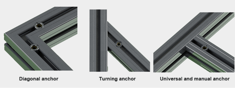

Anchor connectors are divided into three parts: T-shaped connecting pins, threaded pipe sleeves, and top screws. The rear end of the T-shaped connecting pin has a conical groove. During installation, slide the T-shaped connecting pin into the groove of the aluminum profile, Insert the other end into the center hole of another profile and connect it to the threaded pipe sleeve, then use a top screw to lock it, and the fixed connection between profiles is achieved through the displacement generated by locking the conical groove with the top thread;